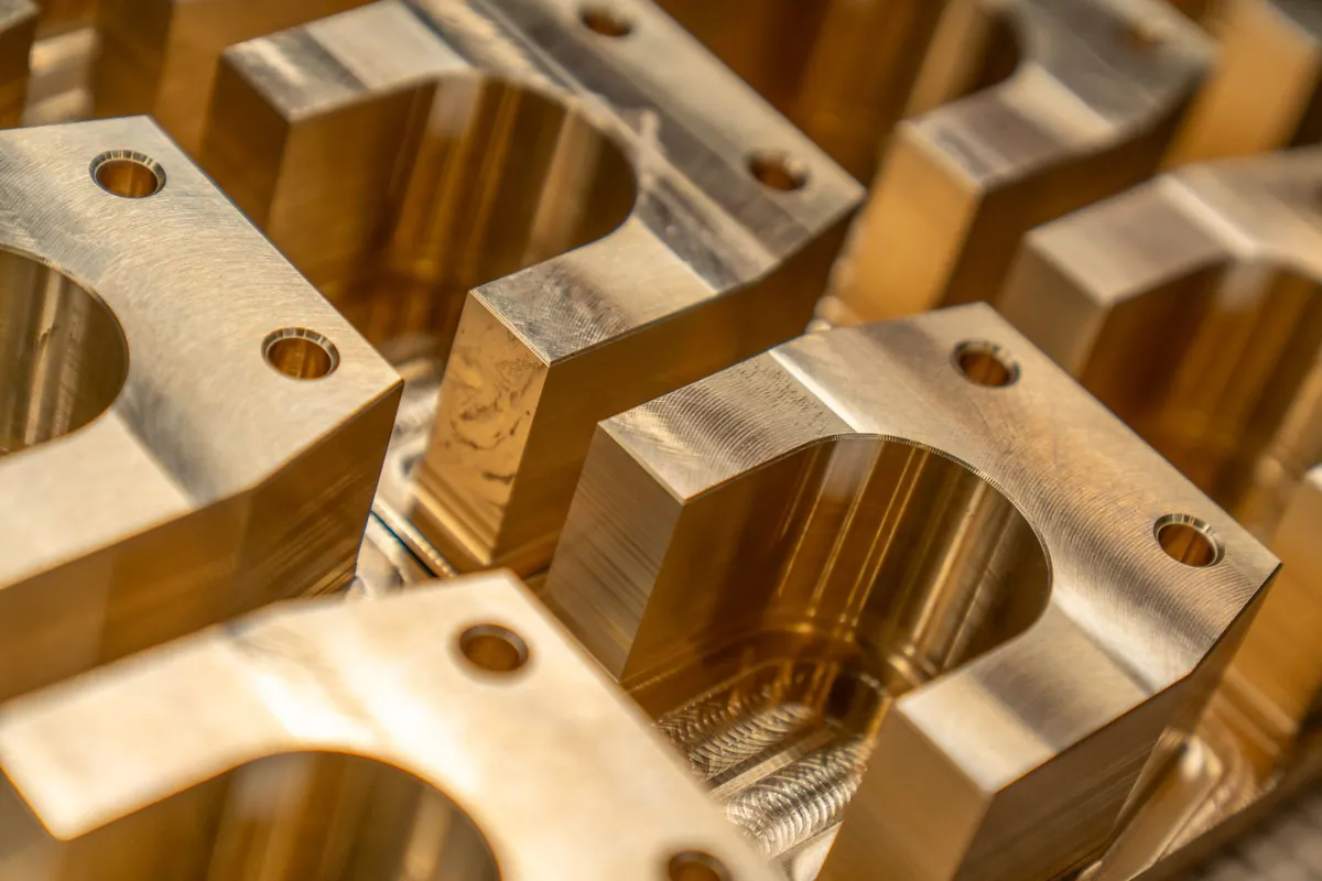
Custom Machining Process and Drawing Specifications for Molybdenum Electrodes
WeiBeam · Electrode solutions for high-temperature melting
The key to custom machining molybdenum electrodes is translating operating parameters into an executable drawing. This article lists the four categories of information needed before inquiry (form, connection, operating conditions and lead time), breaks down the process flow from drawing review to inspection and delivery, and gives drawing annotation rules, recommended tolerances and a comparison of threaded, welded and clamped connections.
Custom machining of molybdenum electrodes is not primarily a matter of lathe precision; it is a matter of translating the operating conditions into a drawing. The same Φ60 mm rod electrode behaves differently when mounted in the sidewall of a glass furnace rather than the top of a rare earth electrolysis cell: connection type, working-section length and surface condition all differ. If the drawing specifies only overall dimensions, the machine shop can only treat the part as a generic item, and rework at assembly often follows. The sections below run through input information, machining flow, drawing annotation, tolerance agreements and inspection and delivery in order.
1. Four Categories of Input to Prepare Before Inquiring
Custom machining is not simply cutting material to size; specifications are determined around the operating conditions. Provide the four categories below in one go so that quotations and lead times are comparable and drawing iterations are reduced.
| Input item | Contents | Common values (reference) |
|---|---|---|
| Form and outline | Rod, plate, bar or special shape; diameter and thickness, overall length | Diameter Φ20–100 mm, length 150–1500 mm |
| Connection type | Thread, welded joint, clamped end, flange | M10–M30, bevel angle per drawing |
| Operating parameters | Working temperature, current density, medium type | 1300–1600 °C glass melt, 1–3 A/cm² |
| Quantity and lead time | Batch size, staged delivery, spare ratio | Scheduled by project; annual usage and single batch stated separately |
The values above are typical values and reference ranges, subject to actual operating conditions and the contract. Operating parameters are not a formality: working temperature determines whether annealing and straightening are needed, current density determines the conductive cross-section and thread contact area, and the medium determines whether the surface needs alkaline washing or special cleaning. Without this information, responsibility is hard to assign when contact heating or assembly interference later occurs.
Quantity information also affects process selection. A single prototype can be machined with general-purpose tooling and conventional allowances, whereas batches of a hundred or more require dedicated fixtures, tool-wear compensation and first-article approval; stating annual usage separately from single-batch quantity lets the supplier judge whether dedicated gauges are worth building. If the project is commissioned in stages, state whether specifications change between stages, so that dies and fixtures built now can be reused.
2. Process Flow from Drawing to Delivery
- Drawing and condition review: confirm material grade, tolerance band, working-section position and service environment;
- Material preparation: select molybdenum bar or plate to specification and verify batch and quality certificate;
- Cutting and billet shaping: saw to length, face the ends, control allowances;
- Main form machining: turn or mill diameter, steps, taper and length;
- Connection machining: cut threads, machine bevels or clamping sections;
- Grinding and surface treatment: finish critical dimensions, deburr, control roughness;
- Cleaning and drying: remove cutting fluid and molybdenum chips to prevent residue;
- Inspection and packing: re-check dimensions, inspect appearance and internal defects, pack moisture-proof and impact-proof, then deliver.
Two hold points in the flow need confirmation: after drawing review and before material release, confirm critical dimensions and tolerance bands; after connection machining, perform a fit-up trial or a thread go/no-go check. The first prevents a whole batch from being reworked, the second prevents discovering insufficient thread engagement only at assembly. Neither check is complicated, yet together they keep most disputes from reaching shipment.
Allowances at the material preparation stage need separate mention. Molybdenum bar length and diameter both carry incoming deviations; if drawing dimensions are set hard against the upper limit of the raw material, the finished length may be short after end facing. The usual practice is to reserve facing allowance on finished length and grinding allowance on diameter; the size of the allowance depends on billet source and straightness, and where incoming bar is visibly bowed the allowance must be larger, otherwise localized black skin remains after turning.
3. What the Drawing Should Specify
Common problems with molybdenum electrode drawings include both under-annotation and over-annotation: outline dimensions are specified in fine detail while the connection is marked "per sample," or roughness is called out face by face on non-critical surfaces, inflating machining cost. We recommend zoning the annotations into four categories so that critical information is concentrated and secondary information simplified.
| Category | Recommended annotations | Frequently omitted |
|---|---|---|
| Body dimensions | Diameter or thickness, overall length, step diameter and length, end form | Step transition radii, end chamfers |
| Connection | Thread specification and hand, bevel form and angle, clamping-section length | Thread run-out, undercut |
| Form, position and surface | Tolerances on critical dimensions, concentricity, perpendicularity, surface roughness | Specification of the measurement datum |
| Marking and packing | Batch marking location and method, individual packing requirements | Marking must not fall on mating surfaces |
The drawing should also state material condition, for example whether it is forged or requires stress-relief annealing. At the same outline dimension, annealing or not changes straightness and the feel of subsequent machining; if the drawing is silent, the supplier delivers the conventional condition, and if the buyer then demands rework, both parties bear the time cost.
For view representation, provide projections in at least two directions and show thread depth, undercut and bore structure in section views. From an outline view alone, the shop cannot tell whether a hole is through or blind, or on which side the bevel is cut. For special shapes, also supply a 3D model or key section dimensions to aid programming and gauge design; where model and drawing disagree, note on the drawing which one governs.
4. How to Set Tolerances Reasonably
At room temperature, molybdenum's toughness and machinability sit between nonferrous metals and brittle materials. Tighter tolerances raise grinding and inspection hours quickly and increase the risk of nonconformance. The reasonable approach is to concentrate tolerances on dimensions that affect assembly and conduction and to leave the rest at conventional accuracy.
| Location | Recommended tolerance (reference) | Note |
|---|---|---|
| Mating diameter | ±0.05–0.15 mm | Fits the clamp seat, flange or electrode hole |
| Overall length | ±0.5–1.0 mm | Affected by billet length and sawing accuracy |
| Concentricity | 0.05–0.10 mm | Between threaded section and working section |
| End-face perpendicularity | 0.05 mm/100 mm | Affects end contact and current distribution |
| Surface roughness | Ra 1.6–3.2 μm | The working section should not be over-polished |
The above are reference ranges, subject to the drawing and contract. If a critical dimension must be tightened to the 0.02 mm level, agree the measurement method and datum at the same time; otherwise the supplier's and buyer's inspection results cannot be aligned, and one electrode yields two verdicts.
The relationship between tolerance and cost can be understood this way: tightening a diameter tolerance from ±0.15 mm to ±0.05 mm usually means adding a finish-turning or grinding pass and switching inspection from calipers to micrometers; tightening further to ±0.02 mm also requires a temperature-controlled environment and dedicated gauges. Buyers should first confirm the actual assembly clearance requirement before deciding to tighten, rather than labeling every dimension as high precision. Steps and end faces that are not part of a fit can stay at conventional accuracy.
5. Comparison of Three Connection Types
The connection type directly determines on-site assembly and later maintenance, so it should be chosen against current magnitude, disassembly frequency and working temperature rather than carried over from a previous drawing.
| Type | Suitable applications | Machining points | Main risks |
|---|---|---|---|
| Threaded connection | Top-inserted and side-inserted electrodes requiring periodic disassembly | Thread length, hand, undercut and run-out | Galling at high temperature, rising contact resistance |
| Welded joint | High current, long working section, fixed installation | Bevel angle, pre-weld cleaning, post-weld inspection | Weld porosity, heat-affected-zone embrittlement |
| Clamped end | Water-cooled clamps, quick-change stations | Clamp-section diameter and length, surface roughness | Slippage at the clamp face, localized overheating |
Threaded connections tend to gall at high temperature; applying a high-temperature anti-seize compound and controlling preload at assembly is more effective than simply lengthening the thread. Welded joints should avoid a transverse weld within the electrode's working section, the bevel and filler must match the base metal, and lack of fusion should be checked after welding. Clamped ends must ensure contact area; where the clamp section is too short, current concentrates on a small area and the end temperature rises noticeably.
For threads, specify the full parameter set on the drawing: size, pitch, accuracy class, hand and engagement length. Electrodes are repeatedly dismantled at high temperature; if threads are machined to ordinary accuracy, the fit clearance is large, contact area is reduced and current flow causes local heating; if the clearance is too small, assembly is difficult and forced tightening damages the thread form. In practice the engagement length is usually held at one to one and a half times the thread diameter, with go/no-go gauge inspection specified instead of judging by feel.
6. Design Constraints Imposed by Molybdenum's Machining Characteristics
Molybdenum has a high elastic modulus and limited room-temperature ductility; slender bars tend to deflect and chatter during turning, and beyond a certain length-to-diameter ratio a steady rest or segmented machining is required. Thin-wall sections and sharp corners are prone to chipping during clamping and cutting, so designs should avoid very narrow grooves and sharp edges; where a sharp internal corner is needed, the drawing can permit a transition radius.
Hole making is similarly constrained. Deep-hole drilling is difficult to clear chips from, and molybdenum chips pack in the hole and break tools; the usual recommendation is to keep hole depth within a certain multiple of the hole diameter and switch to segmented machining or EDM beyond that. Thread forms should not be too fine, since fine threads strip more easily during assembly; if a fine thread is mandatory, the contract should fix the inspection method and go/no-go gauge specification.
Clamping method affects residual stress and straightness. When a three-jaw chuck grips a thin-wall or large-diameter tubular part, clamping force easily produces elastic deformation of the section, which springs back after release, so the measured size differs from the machined size. Long bars should be machined with a steady rest at both ends and in multiple passes, avoiding a single heavy cut that concentrates cutting heat. If straightness is out of tolerance after machining, correct it by straightening and stress relief rather than forcing it with subsequent grinding.
7. Surface Treatment and Cleaning
Residues on machined surfaces include cutting fluid, molybdenum chips and oxidation tint. Alkaline washing removes grease; acid pickling carries a hydrogen-embrittlement risk, so time must be strictly controlled and thorough drying must follow. Whether the glass-contact working section is polished depends on the duty: moderate roughness aids stable wetting, while over-polishing adds cost without necessarily adding benefit.
Cleanliness should not be judged by eye alone. For cleanliness-sensitive duties such as pharmaceutical glass and crystal growth, the contract can specify wipe checks and residue testing to be completed before packing. If parts cannot be packed promptly after cleaning, they should be held in a dry environment to prevent the surface from re-adsorbing moisture.
8. Inspection and Shipping Documents
Final inspection typically covers dimensional re-check, visual inspection, and confirmation of material and density, with ultrasonic testing and thread go/no-go checks added where required. Shipping documents generally include the material certificate, dimensional inspection records and batch identification, prepared in line with the relevant requirements of YS/T 1312-2019. Consistency between documents and physical goods is the basis for later traceability.
On receipt, we recommend re-measuring critical dimensions against the same datum and keeping first-article records. If a deviation is found, first confirm that the measurement datum and temperature conditions match, then judge whether it is a machining issue or a measurement difference. For batch deliveries, the sampling ratio and acceptance rules should be written into the contract in advance so that each batch is not judged by a different yardstick.
Packing matters for low-toughness long parts such as molybdenum electrodes. Each electrode should have spacers and end protection, and fixing points in the crate should avoid the working section and threads to prevent impact damage in transit. Sea or long-distance shipments also need moisture protection so that water stains and oxidation tint do not appear on opening. The packing method should be written into the drawing or technical agreement rather than negotiated just before dispatch.
9. Linking Prototyping to Volume Production
For new or revised parts, start with a single prototype focused on validating connection fit and working-section dimensions rather than chasing volume pricing first. Once the prototype is approved, freeze the critical dimensions, tooling and process parameters into the work instructions so that volume production has a stable baseline. For staged deliveries, agree the identification method for each batch so that field usage can be tracked by batch.
Reliable delivery of custom orders depends on closing the loop across drawing confirmation, process confirmation and inspection confirmation. Miss any one and the problem surfaces at assembly or on the furnace. For connection types and working-section requirements for glass furnace electrodes, refer to that product's specifications; for crucible and electrode fit-up in crystal growth hot zones, see the crystal growth electrode page; general entries on machining and materials can be browsed by topic.
Frequently asked questions
What steps make up the process flow from drawing to delivery?
The flow falls broadly into five stages: drawing review, billet preparation, machining, inspection and packing and delivery. After drawing review and before material release there is a hold point to confirm critical dimensions and tolerance bands, because molybdenum bar length and diameter both carry incoming deviations; if drawing dimensions are set hard against the raw material upper limit, the finished length may be short after end facing.
What design constraints do molybdenum's machining characteristics impose?
Molybdenum has a high elastic modulus and limited room-temperature ductility. Slender bars tend to deflect and chatter during turning, and beyond a certain length-to-diameter ratio a steady rest or segmented machining is required.
What do inspection and shipping documents cover?
Shipping documents generally include the material certificate, dimensional inspection records and batch identification, prepared in line with the relevant requirements of YS/T 1312-2019. Final inspection typically covers dimensional re-check, visual inspection, and confirmation of material and density, with ultrasonic testing and thread go/no-go checks added where required.
Note: this article shares general industry and technical information and is not purchasing, investment or legal advice. Specific parameters and results are governed by the mutual technical agreement and factory inspection records.
Standards note: electrodes are controlled to YS/T 1312-2019 Molybdenum Electrodes; molybdenum rods to ASTM B387 / GB/T 17792; molybdenum plate and discs to ASTM B386 / GB/T 3876. Parameter ranges in this article summarise public technical data and engineering practice — actual values vary with furnace conditions and are governed by the technical agreement and inspection records.
Related products
Electrodes and high-temperature molybdenum parts for this duty — specifications and selection notes are on the product pages.
Product information
Glass melting furnace molybdenum electrode
For electric boosting and all-electric melting of container, packaging, pharmaceutical, photovoltaic and electronic glass, compatible with mainstream refractories and furnace designs.
View specifications →
Crystal growth molybdenum electrode
For heating in Czochralski growth furnaces for sapphire, optical crystals and laser crystals; high purity and high-temperature stability.
View specifications →
Rare-earth electrolysis molybdenum electrode
For high-temperature molten-salt electrolysis of rare-earth metals; good conductivity, molten-salt erosion resistance and stable cell operation.
View specifications →