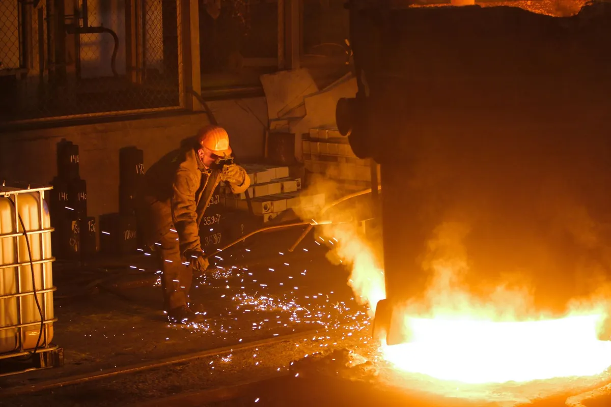
Co-Designing Waste Heat Recovery and the Electrode System in a Furnace
WeiBeam · Electrode solutions for high-temperature melting
When waste heat recovery is added to a glass furnace, the heat distribution inside the furnace changes and the heat balance of the electrode zone has to be recalculated. This article explains how heat extraction affects furnace pressure and the temperature regime, analyzes the interaction between electrode cooling, insulation and current distribution, and lists the items to check in parallel during implementation so that local overheating or undercooling can be avoided.
Waste heat recovery is often treated as an add-on device on the flue, but in practice it changes how heat is distributed inside the furnace. How much heat is extracted and from where affects furnace pressure, flame shape and glass melt convection, and the thermal state of the electrode zone changes with them.
Waste Heat Recovery Changes the Heat Distribution
Extracting flue gas downstream of the regenerator or at the flue lowers the downstream temperature and may also change the negative pressure inside the furnace. If the extraction rate is too high, the flame is drawn toward the flue, the fining zone temperature drops and the batch melting rate changes with it. If the recovered heat is used to preheat combustion air, the heat entering the furnace rises again, creating a disturbance in the opposite direction. In design, the extraction point, extraction rate and reuse method should be adjusted as one set of parameters rather than fixed separately. The location also changes the scope of the effect: extraction close to the regenerator disturbs furnace pressure more directly, while extraction at the end of the flue gives a lower waste gas temperature and less recovery value.
The Temperature Regime of the Electrode Zone Must Be Recalculated
Electric boosting electrodes are immersed in the glass melt and use Joule heat from the current to hold the local temperature. Once the overall heat distribution in the furnace changes, the temperature field at the same power shifts. What can happen is this: the fining zone runs short of heat, operators raise the electrode power, and the area around the electrode then overheats, accelerating corrosion. The remedy is to map electrode power distribution to the furnace temperature measuring points and regulate by zone rather than by total. Thermocouple locations should also be reviewed so that a measuring point does not sit in a recirculation zone and fail to read the true temperature. When the insertion depth of the electrode changes, the current path and the location of local heating change with it; if the glass level was adjusted during the retrofit, the insertion depth and power curve must be rechecked.
| Item | Values and notes |
|---|---|
| Standard sizes | Rod diameter Φ20–100mm, length 150–1500mm (custom sizes to drawing) |
| Applicable standards | YS/T 1312-2019 Molybdenum Electrodes; molybdenum rods follow ASTM B387 / GB/T 17792, molybdenum plates and discs follow ASTM B386 / GB/T 3876 |
| Service temperature | About 1300℃ continuous, about 1600℃ short-term maximum |
| Operating current density | 1–3A/cm² |
Cooling and Insulation Must Be Checked Together
The heat carried away by electrode cooling water depends on electrode power and insertion depth. If the overall furnace temperature falls after the waste heat retrofit and the cooling water flow is not adjusted, the area around the electrode may be overcooled, raising the viscosity of the glass melt and interfering with fining. Conversely, if the insulation layer is thickened without adequate cooling, a local hot spot easily forms around the electrode. During the retrofit, put cooling water flow, inlet-to-outlet temperature difference and insulation thickness on the same heat balance sheet and check them item by item. A sudden widening of the cooling water temperature difference may mean insufficient flow or local scaling; check the instruments before touching the equipment so as not to mistake it for a heat balance problem.
Items to Check During Implementation
- Carry out a heat balance calculation before and after the retrofit, recording the extraction rate, furnace pressure and the temperature at each measuring point.
- Confirm how the electrode power distribution scheme interlocks with the furnace temperature control loop.
- Check the cooling water flow and temperature rise settings, and verify the calibration status of the flow meters and thermometers.
- Assess the suitability of the insulation material under the new temperature gradient, paying attention to expansion joints.
- Set the inspection frequency for the first period of operation, focusing on the electrode base and the brick joints.
During the first two weeks after start-up, increase the inspection frequency and record temperature, flow and power on the same sheet so that trends are easy to spot.
The key to co-design is to adjust the furnace, the electrodes and the waste heat system as one whole rather than optimizing each in isolation. An extra round of heat balance calculation before the retrofit will leave far fewer fluctuations after start-up.
Frequently asked questions
How does waste heat recovery change the heat distribution inside a furnace fitted with molybdenum electrodes?
Extracting flue gas downstream of the regenerator or at the flue lowers the downstream temperature and may also change the negative pressure inside the furnace. If the recovered heat is used to preheat combustion air, the heat entering the furnace rises again, creating a disturbance in the opposite direction.
In what order should the implementation-stage checks be carried out?
Check the cooling water flow and temperature rise settings, and verify the calibration status of the flow meters and thermometers. Set the inspection frequency for the first period of operation, focusing on the electrode base and the brick joints.
Note: this article shares general industry and technical information and is not purchasing, investment or legal advice. Specific parameters and results are governed by the mutual technical agreement and factory inspection records.
Related products
Electrodes and high-temperature molybdenum parts for this duty — specifications and selection notes are on the product pages.
Product information

Glass melting furnace molybdenum electrode
For electric boosting and all-electric melting of container, packaging, pharmaceutical, photovoltaic and electronic glass, compatible with mainstream refractories and furnace designs.
View specifications →
Molybdenum disc
Circular sheet made from high-purity molybdenum powder by powder metallurgy and rolling; used for furnace heating elements, heat shields, boats and sputtering targets.
View specifications →
Molybdenum rod and shaft
Rod and shaft diameters beyond wire: Ø0.5–25mm drawn or swaged shafts and Ø16–300mm forged or sintered rods, for vacuum electronics, guide rods, electrodes and heating elements.
View specifications →